Service
Tasks
○Purpose : Here, we will learn about the various tasks the service person is
expected to carry out to perform for the purpose of maintaining a specific level
of machine performance.
●Outline
Let’s take a look at the tasks of the service
person associated with the fixing system. To obtain a detailed description,
click the appropriate item.
|
1. Parts Replacement
Some parts of the machine require adjustment
or counter initialization in service mode upon replacement. If you have replaced
any of the following, go through the steps given:
■Fixing Film Assembly
If you have replaced the fixing film
assembly, you will have to reset the fixing film assembly life counter so that
the count will start anew.
Make the following selections in service mode
to reset the counter:
COPIER > COUNTER > DRBL-1 >
FX-FILM
■Pressure Roller
If you have replaced the pressure roller, you
will have to reset the pressure roller life counter so that the count will start
anew.
Make the following selections in service mode
to reset the counter:
COPIER > COUNTER > DRBL-1 >
FX-LW-RL
■Fixing Cleaning roller
If you have replaced the fixing cleaning
roller, you will have to reset the fixing cleaning roller life counter so that
the count will start anew.
Make the following selections in service mode
to reset the counter:
COPIER > COUNTER > DRBL-1 >
FX-CL-RL
■Pressure roller
bushing
If you have replaced the pressure roller
bushing, you will have to reset the pressure roller bushing life counter so that
the count will start anew.
Make the following selections in service mode
to reset the counter:
COPIER > COUNTER > DRBL-1 >
FX-LW-BR
Each life count is kept in memory on the DC
controller PCB. If you have to replace the DC controller PCB, be sure to enter
the count that has been read of the previous PCB.
2. Maintenance
Servicing
The service person is expected to replace,
clean, or check the following at specific intervals; perform the work when the
end of individual intervals approach:
| Item | Parts name |
Task
|
Approximate
interval
|
Remarks
| |
| Periodically replaced parts | - | - | - | The fixing assembly does not have parts that must be replaced periodically. | |
| Durables | Fixing film unit |
iR2270/2870
|
replace
|
every 150,000 prints
|
|
|
iR3570/4570
|
replace
|
every 240,000 prints
|
|||
| Pressure roller |
iR2270/2870
|
replace
|
every 150,000 prints
|
||
|
iR3570/4570
|
replace
|
every 240,000 prints
|
|||
| Fixing cleaning roller |
iR2270/2870
|
replace
|
every 150,000 prints
|
||
|
iR3570/4570
|
replace
|
every 240,000 prints
|
|||
| Pressure roller bushing |
replace
|
every 300,000 prints
|
|||
| Periodical serving | Fixing inlet guide |
clean
|
every 120,000 prints
|
Dry wipe with lint-free
paper.
| |
| Film bias static eliminator | iR2270/2870 | clean | every 150,000 prints | Dry wipe with lint-free paper. | |
| iR3570/4570 | clean | every 240,000 prints | Dry wipe with lint-free paper. | ||
3.
Troubleshooting
■E000 through 003 (fault in fixing
assembly)
If a fault occurs in the fixing assembly, go
through the following: (You will have to reset the error code after performing
these steps.)
1) replace the fixing film unit.
2) check the connectors between the fixing film unit and the DC
controller.
3) replace the DC
controller PCB.
■E007-0000 (fixing film rotation
error)
If a fault occurs in the rotation of the
fixing film, go through the following to correct it. (You will need to reset the
machine after performing these steps.)
1) check the machine as a whole, and check particularly the gear used to
drive the pressure roller of the fixing assembly; then, replace any damaged
part.
2) check the marker of the fixing film; if soiled or damaged, clean with
lint-free paper or replace the fixing film unit.
3) check the connectors between the fixing film speed sensor (PS8) and
the DC controller.
4) replace the fixing film speed sensor
(PS8).
5) replace the DC controller PCB.
■Setting Fixing Film Cleaning
Intervals
By default, the machine cleans the fixing
film only in the event of a jam; nevertheless, you can change the intervals by
making the following selections in service mode so that the machine will clean
the film regardless of jam removal:
COPIER > OPTION > BODY > FIX-CON
(Category 2)
0: clean only in response to jam (default)
1: clean during last rotation every 500 prints
2: clean during last rotation every 200 prints
3: clean during last rotation every 100 prints
■Soiling at Specific
Intervals
The presence of a scratch or dirt on a roller
of the fixing assembly will show up as a cyclic fault in output images. You can,
therefore, identify the cause of a cyclic fault based on the interval of its
occurrence.
If a cyclic fault is noted, consult the
following table to identify the cause (roller).
|
Parts name
|
Image fault
|
Interval
|
Remedy
| |
|
Fixing film
|
soiling at specific
interval
(face of paper)
|
76 mm (approx.)
|
Clean or replace the fixing film
unit.
| |
|
Pressure roller
|
soiling at specific
intervals
(back of paper)
|
iR2270/2870
|
79 mm (approx.)
|
Clean or replace the pressure
roller.
|
|
iR3570/4570
|
95 mm (approx.)
| |||
|
Delivery roller
|
Soiling at specific
internals
(face of paper)
|
42 mm (approx.)
|
Clean or replace the delivery
roller.
| |
4. Points to Note About
Servicing
■When Handling the Fixing
Assembly
∙Be sure to turn off the power before removing the fixing
assembly.
The fixing assembly is extremely hot immediately after printing. Be
sure to leave the machine alone for some time before touching the fixing
assembly.
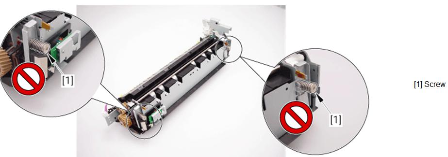
∙Do not ever turn the screw used to lock the fixing film
in place. Otherwise, the nip pressure will be affected, possibly leading to
fixing faults and jams.

■Points to Note When Handling the Fixing Film
Unit
∙ Do not disassemble the fixing film unit in the
field.
∙ Do not touch the surface of the fixing film, and take care not to
damage it.
■Resetting Error Codes
If a fault indicated by a jam code E000
thorough E003 (fault in the fixing assembly) occurs, merely turning off and then
on the main power switch will not reset the machine. Make the following
selections in service mode to reset the machine:
1) remove the causes of the error.
2) in service mode, make the following selections, and press the OK
key.
3) turn off and then on the power switch.
■Compatibility of the Fixing
Assembly
The fixing assembly of the iR2270/2870 Series machine
and that of the iR3570/4570 Series machine are not compatible.
You will not be able to physically install the wrong assembly because of the difference in the number of pins on the AC connector. Check the number of pins before fitting a fixing assembly into the machine.
You will not be able to physically install the wrong assembly because of the difference in the number of pins on the AC connector. Check the number of pins before fitting a fixing assembly into the machine.

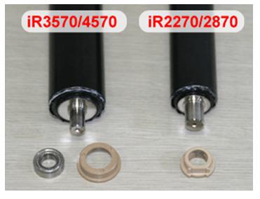
The iR2270/2870 Series machine and the
iR3570/4570 Series machine also differ in terms of assembly components as can be
learned from the following table:
| |||||||||||||


0 Reviews:
แสดงความคิดเห็น